

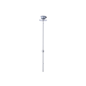
Main application
Level indication, alarming and control of various liquids.
Main feature
Insensitive to process conditions such as pressure, temperature and specific gravity.
Integrated protection circuit protects connected devices in the event of product fault or overcurrent.
Various wetted parts material available for specific application
Easy-to-use controller. (MP2000)
Analog output (2 wire, 4 to 20mA DC) available as standard.
Improved long-term stability.
Hall ICs improved long-term stability.
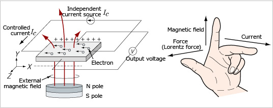
When current flows in an X direction on a semiconductor, electrons move in the opposite direction. When an external magnetic field is applied in a Y direction, electrons experience an electromagnetic force.
A left hand can represent these three mutually orthogonal axes: force on the thumb, field on the first finger and current on the second finger. (Fleming’s left-hand rule)
The change in the strength of the magnetic field causes change in strength of the electric field, changing the output voltage proportionally. This is called the Hall effect. Hall ICs utilize this effect.
- Hall effect sensor is magnetic sensors that use Hall effect. They give electric signals due to presence of a magnetic field from a magnet or an electric field from current flow.
- Hall IC incorporates a magnetic sensor (Hall effect sensor) and another IC that converts output from the sensor to a digital signal. Hall IC is comprised of 3 terminals: input, GND and output.
- The sensor is used for position detection of throttle, pedal or suspension for vehicle installations, and absolute position detection or proximity switching.
Principle of Operation
The product is comprised of a float and a stem. The float has a magnet inside. The stem incorporates a circuit board with several Hall ICs and resistors placed at regular intervals.
Fig.1 shows operation of the float and the Hall ICs. Fig.2 shows the circuit in the stem.
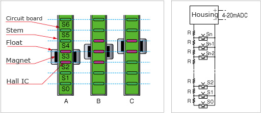
Fig. 1: Operation of float and Hall ICs
Fig. 2: Circuit in the stem
For a rising level, float location and Hall ICs in operation change as shown in Fig.1, from A(2 ICs in operation) to B (3 ICs in operation), then to C (2 ICs in operation). For a falling level, from C to B, then to A.
This means that the combined resistance changes as the float rises or falls. The electronics in the sensor housing measures the combined resistance, converts it to signals, and then amplify and calibrate the signals to give current output (2 wire, 4 to 20mA DC).
Voltage output is also available by connecting a current-to-voltage converter or a precision resistor to the output terminal.